




'/%3E%3C/svg%3E)
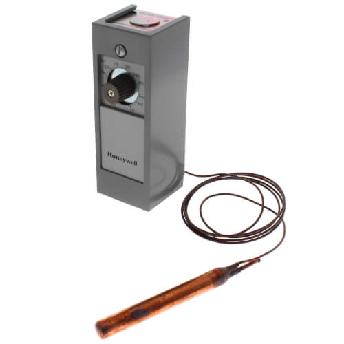
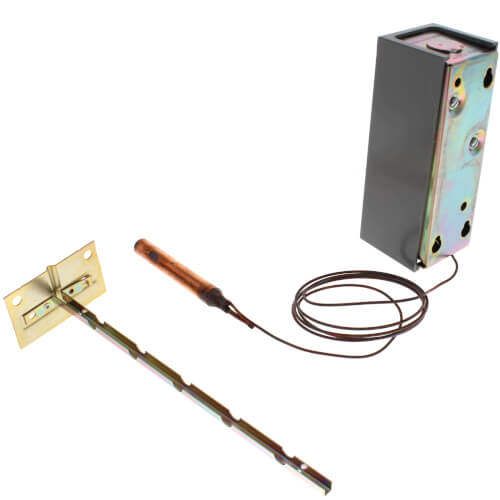
Remote bulb Commercial Temperature Controller, 55 F to 175 F, 5 ft. capillary, Copper bulb sensing element
 --%3E %3Csvg version='1.1' id='No-RB' xmlns='http://www.w3.org/2000/svg' xmlns:xlink='http://www.w3.org/1999/xlink' x='0px' y='0px' viewBox='0 0 100 100' enable-background='new 0 0 100 100' xml:space='preserve'%3E %3Cpath fill='%23CECECE' d='M79.44,0.95H20.56C9.78,0.95,0.95,9.78,0.95,20.56v58.87c0,10.79,8.82,19.61,19.61,19.61h58.87 c10.79,0,19.61-8.83,19.61-19.61V20.56C99.05,9.78,90.22,0.95,79.44,0.95z M65.38,58.24l9.38,29.58L49.69,69.78L24.5,87.82 l9.34-29.6L8.8,39.6l30.73-0.17c0,0,6.98-19.61,10-28.93c0.54,1.36,9.88,29.1,9.88,29.1H91.2L65.38,58.24z'/%3E %3C/svg%3E)


MANUALS (2)
Product Highlights


Description
Specifications
- Application: Regulates temperature of air or liquids in ducts, pipes, tanks and boilers
- Output Type: Relay
- Type: Remote Bulb
- Output: SPDT
- Voltage: 120 Vac or 240/277 Vac
- Frequency: 50, 60 Hz
- Dimensions: 5-5/8 in. high x 2 in. wide x 2-5/8 in. deep
- Sensor Element: Copper bulb
- Number of Sensor Inputs: 1
Features
- Suitable for applications requiring temperature control of air or liquids where controller must be placed outside the sensing area.
- Typical uses include control of dampers and valves in heating, cooling and heating-cooling systems.
- Fast response models (available for use in return air duct) operate approximately four times faster than standard models.
- Controller can be mounted in any position.
- Ambient temperature compensation provides good temperature control.
- Refer to T775 Electronic Remote Temperature Controller where more exact control is required and/or remote controller location is preferred.
- T675A models with fixed differential have an electrical rating of 125 VA at 120/208/240 and 277 Vac.
- T675B models have 125 VA pilot duty up to 277 Vac.
- T678 models have a maximum connected load of 2000 VA.
Specs
| Application: | Commercial Remote Bulb Temperature |
|---|---|
| Output: | Relay SPDT |
| Voltage: | 277v 240v 120v |
| Hertz: | 60 50 |
| Contact Ratings 120v: | 8.0 AFL 48.0 ALR |
| Contact Ratings 240v: | 5.1 AFL 30.6 ALR |
| Contact Ratings 277v: | 4.2 AFL 25.2 ALR |
| Height: | 5-5/8" |
| Width: | 2" |
| Depth (Inches): | 2-5/8" |
| Sensor Type: | Copper Bulb |
| Sensor Inputs: | 1 |
| Capillary Length: | 5 ft. |
| Bulb Size: | 1/2" x 3-9/16" |
| Max Temp (F): | 175°F |
| Temperature Range (F): | 55°F to 175°F |
| Min Temp (F): | 55°F |
| Max Operating Temp: | 200°F |
| Differential: | 3.6° to 12°F |

Questions?
You May Also Need
Product Reviews
Be the first to write a review.
Product Q&A
2 QuestionsQ: I am lookingat a honeywell t675a 1540 temperature controller. It has all the specifications I need but I would like to possibly have a longer capillary length , perhaps 10ft. Do you offer one and what would be the model number and price?
Asked by Jon 3 years ago
Add your answer
Verified Reply- SupplyHouse StaffHi Jon. For an alternative with a 20' capillary length, please see SKU: T675A1425 - https://www.supplyhouse.com/Honeywell-T675A1540-Remote-bulb-Commercial-Temperature-Controller-55-F-to-175-F-5-ft-capillary-Copper-bulb-sensing-element
Q: I see three electrical screw terminals on the T675A. The instructions do not clearly show what they represent. Is the middle terminal merely a ground terminal? TOP Terminal: O MIDDLE Terminal: O BOTTOM Terminal: O
Asked by Al 14 years ago
Add your answer
Look closely, in good light they are marked. The center is Common, the top one is normally open, the bottom one is normally closed. I believe the instructions covers this. You are either going to want this switch to close at the desired temperature setting or open. Probably close at temp.
Sorry it took so long to get back to you. The top screw "R" is where you connect the wire that would start any equipment on temperature fall. The middle screw "B" is where you connect the hot wire. This is the common terminal. The bottom screw "W" is where you connect the wire that would start any equipment on temperature rise. You probably only want to use either the "R" or "W" terminal, not both. There is a green screw at the bottom of the frame for grounding the T675A. Hope this helps.