

'/%3E%3C/svg%3E)
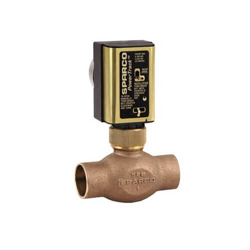
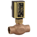
1-1/4" Sweat Motorized Zone Valve, w/ auxiliary switch
' fill='%23F15C02' d='M49 0C21.938 0 0 21.938 0 49s21.938 49 49 49 49-21.938 49-49S76.062 0 49 0m0 82.709a7.54 7.54 0 1 1 0-15.08 7.54 7.54 0 0 1 0 15.08m7.54-28.412a7.541 7.541 0 0 1-15.08 0V22.831a7.54 7.54 0 0 1 15.08 0v31.466z'/%3E%3C/svg%3E)
MANUALS (1)
Product Highlights
Description
Honeywell MZV Series is the first linear zone valve with a built-in balancing plug that permits pre-balancing for each zone.
Specifications
- Application: Residential or Commercial Zoning for hot water heating or chilled water air conditioning systems, fan coil units or indirect water heater service.
- Body Pattern: Two-way
- Maximum Close-off Pressure (psi): 17.5 Psi
- Maximum Water Pressure (psi): 125 Psi
- Maximum Ambient Temperature (F): 125F
- Voltage: 24 Vac
- Frequency: 60 Hz
Features
- Rack and pinion linear design.
- Fast acting, 15 seconds to open, 5 seconds to close.
- Two piece rack design to extend service life.
- Low power consumption, 8 valves, 40 VA transformer.
- External valve position indicator.
- Quiet operation, no water hammer.
- Built-in tamper resistant balancing valve for pre-balancing.
- High torque, constant speed synchronous motor.
- Cooler running, longer life motor.
- Operator can be replaced without draining system.
- Manual opening feature.
- Replaceable valve cartridge.
- Large adjustable flow, 1/2 in. 3/4 in. Cv 5.8; 1 in. 7.0 Cv; 1-1/4 in. Cv 7.0.
- Motor CSA recognized.
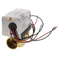
- 4 wire operator with auxiliary switch.
- 2 wire without switch, 24 in. leads.
- Compatible with programmable thermostats.
- Bronze casting; brass/stainless trim
Specs
| Application: | Zoning |
|---|---|
| Size: | 1-1/4" |
| Connection Type: | Sweat |
| Flow Capacity (Cv): | 7 |
| Body Pattern: | 2-Way |
| Max Close-Off PSI: | 17.5 psi |
| Max Pressure (PSI): | 125 |
| Max Ambient Temp (°F): | 125°F |
| Auxiliary Switch: | SPST |
| End Switch: | Yes |
| Voltage: | 24V |
| Position: | Normally Closed |
| Hertz: | 60 |
| Amperage: | 0.25 |
| Time Cycle: | 10-20 Seconds Open, 3-6 Seconds Close |
| Wiring: | 18" Leads |
| Material: | Bronze |
| Max Temp (F): | 240°F |
| Width (Inches): | 3.8" |
| Depth (Inches): | 2-2/5" |
| Height (Inches): | 5.8" |

Questions?
Compare Similar Products
Product Reviews
This may be the last inventory in the US?
SupplyHouse
HoneywellMZV zone valve
Works as intended
Product Q&A
1 QuestionQ: wiring valve? I have 2 red & 2 yellow wires coming out of valve head . There is no wiring instructions. it is a 24 v.-0.7a head part number 500-1 rp. it is a sparco which i know now is honeywell.
Asked by jim 14 years ago
Add your answer
Please see pages 3 & 4 of the following for diagrams: http://s3.pexsupply.com/manuals/1258494532382/19598_PROD_FILE.pdf
Jim- On my older Sparco, yellow/orange were for power 22-28 volt AC, the two red are for an internal limit switch used for boiler control (i.e. boiler won't fire unless valve is open). Use a meter to check for an open on the red wires with a closed valve. You can also manually open this valve which should make continuity between the red leads.
Jim, You need a cheap voltmeter. Two of the wires run the motor which opens the valve. The other two go to a switch that closes when the valve is completely closed. Normally the thermostat circuit applies 28vac to the motor as long as the valve is to be held open, and all the switches on all the valves in the system are wired in parallel to turn on the boiler relay. My units have much smaller wires for the switch, and they are red. If you test them with an ohm meter they will test open since the valve is closed. If you test the motor wires they will show some resistance, I'm guessing maybe a hundred ohms or so. Hope this helps. Cheers, Mark