

'/%3E%3C/svg%3E)
Hover image to zoom
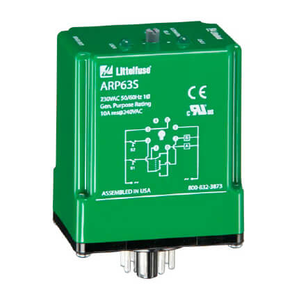
SPDT 8 Pin Alternating Relay (120V)
Hover image to zoom
$170.34 each
In Stock
Get 2 Tue, Jul 7
Order by today, receive Tuesday
MANUALS (1)
Free Shipping This item ships free
Easy Returns No restocking fee for 90 days
Product Highlights
–
120v
Description
–
The ARP Series is used in systems where equal run time for two motors is desirable. The selector switch allows selection of alternation of either load for continuous operation. LED’s indicate the status of the output relay. This versatile series may be front panel mounted (BZ1 accessory required) or 35 mm DIN rail mounted with an accessory socket.
When the rotary switch is in the “alternate” position, alternating operation of Load A and Load B occurs upon the opening of the control switch S1. To terminate alternating operation and cause only the selected load to operate, rotate the switch to position “A” to lock Load A or position “B” to lock Load B. The LEDs indicate the status of the internal relay and which load is selected to operate.
Note: Input voltage must be applied at all times for proper alternation. The use of a solid-state control switch for S1 may not initiate alternation correctly. S1 voltage must be from the same supply as the unit’s input voltage (see connection diagrams on datasheet). Loss of input voltage resets the unit; Load A becomes the lead load for the next operation.
Specifications:
- Input Voltage (V): 24 120 or 230VAC
- Input Tolerance (%): 24VAC: -15% - 20%; 120and230VAC: -20% - 10%
- Input AC Line Frequency (Hz): 50/60Hz
- Maximum Output Voltage (V): 250VAC
- Output Type: Electromechanical Relay
- Output Form: SPDT DPDT cross wired DPDT
- Output Load Rating (VA): 10A resistive @ 120/240VAC and 28 VDC; 1/3hp @120 / 240VAC
- Isolation Voltage (V): 1500V RMS input to output
- Life: Mechanical - 1 x 10⁷; Electrical - 1 x 10⁶
- Termination Type: Octal 8-pin or magnal 11-pin
- Mounting Method: Plug-in socket
- Operating Temperature: -20° to 60°C (-4°F to 140°F)
- Storage Temperature (F/C): -30° to 85°C (-22°F to 185°F)
- Dimensions: 3.20 x 2.39 x 1.78 in. (81.3 x 60.7 x 45.2mm)
Specs
–
| Product Type: | Relay |
|---|---|
| Voltage: | 120v |
| Switch: | SPDT |
| Output: | 8-pin = SPDT |
Contact
+

Happy Independence Day!
Our Customer Support will be closed today in honor of Independence Day. We will be back tomorrow to answer your questions.
Call or text 888-757-4774
Special Hours
Closed Now
Monday – Thursday
8am–7:45pm
Friday
9am–7:45pm
Saturday – Sunday
9am–5:45pm
You May Also Need
Free Shipping
On orders over $99
We offer flexible shipping and scheduling options, up-to-date delivery estimates, and free ground shipping on any order over $99 to make sure your order gets to you on-time, for less.
Shipping PolicyEasy Returns
Returning items is as simple as 1-2-3
Ordered the wrong product? Item damaged in transit? Our 3-step process makes returning products easy – even up to a year after purchase – with no restocking fees on returns made within 90 days.
Return Policy