

'/%3E%3C/svg%3E)
Hover image to zoom
Hover image to zoom
$84.99 each
In Stock
Get 46 Tue, Jun 9
Order by today, receive Tuesday
Free Shipping On orders over $99
Easy Returns No restocking fee for 90 days
Description
–
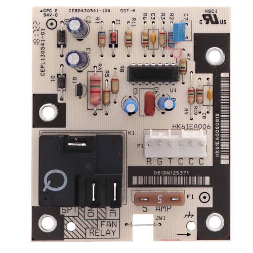
Carrier HK61EA006 Circuit Board w/ Time Delay Relay
An OEM replacement printed circuit board used in compatible Carrier fan coil/air handler applications to provide blower control functions, including time-delay operation, as defined by the manufacturer.
Key Features:
Compatibility & Applications:
Installation & Operation Notes:
Maintenance & Troubleshooting:
User Reviews & Q&A Summary:
An OEM replacement printed circuit board used in compatible Carrier fan coil/air handler applications to provide blower control functions, including time-delay operation, as defined by the manufacturer.
Key Features:
- Official OEM Circuit Board w/ Time Delay Relay for Carrier HVAC equipment
- Carrier service documentation for the CES013003-00/01 control boards (HK61EA002, HK61EA006) describes board features including low-voltage thermostat connections, a 5-amp low-voltage fuse, a fan relay, and time-delay functionality
Compatibility & Applications:
- Covered in Carrier service documentation as the Fan Coil Printed Circuit Board (HK61EA006) within the CES013003-00/01 control board family (also references HK61EA002)
- Used in Carrier fan coil/air handler product servicing as documented in the SM-FANCOIL-07 service manual (fan coil/air handler platforms are referenced in the manual, including FB4C, FX4D, PF4, FF1E, and FZ in related control-box context)
- Must only be used where the manufacturer specifies this exact part number: HK61EA006 for the specific unit/model being serviced
Installation & Operation Notes:
- Installation should be performed by a qualified HVAC service professional
- Follow the unit's service/installation manual and wiring schematics for the specific equipment; the Carrier service manual directs technicians to use the wiring schematics as a guide when servicing/troubleshooting the PCB
- Safety note shown in the Carrier documentation: disconnect remote power supply before opening the panel
- Q&A guidance emphasizes verifying the correct board using the unit's product ID/model/serial information; the board does not include a wiring harness, and the harness is sold separately (Carrier 327905-701)
Maintenance & Troubleshooting:
- Carrier troubleshooting guidance (board-level) includes scenarios such as: fan will not turn on from thermostat, electric heat staging issues, transformer fuse repeatedly blowing, and fan running continuously
- Carrier notes that overheated/blown traces on the PCB typically indicate a high-voltage short or high voltage applied to the low-voltage circuit, and stresses confirming correct wiring before applying power
- Carrier troubleshooting steps also call out checking transformer primary/secondary voltage, verifying correct R/C wiring, and replacing an identical 5-amp fuse if blown (and investigating shorts/excess VA draw/miswiring if it continues to blow)
User Reviews & Q&A Summary:
- Reviews commonly describe it as an exact-fit OEM replacement that restores normal blower/air-handler operation when the original board or relay components are damaged (often reported after burned/melted board components or loss of airflow)
- A recurring theme is straightforward replacement for experienced installers (multiple reviewers mention easy install and significant cost savings versus service calls)
- Q&A themes focus on confirming compatibility by product ID/model/serial (especially when board label digits differ), and confirming it does not include the wiring harness; wiring diagrams/installation guidance are generally directed back to Carrier documentation or Carrier support

Questions?
Speak with a real person who will go out of the way to help!
Call or text 888-757-4774
Monday – Thursday
8am–7:45pm
Friday
9am–7:45pm
Saturday – Sunday
9am–5:45pm
Compare Similar Products
Brand
You May Also Need
Product Reviews
5 out of 27 reviews
100% would recommend this product
5 star
100%
4 star
0%
3 star
0%
2 star
0%
1 star
0%
Customer Images
Showing 1-10 of 27 reviews
I would buy from this company again
Thank you for your fast service and shipping. The item was exactly as the one that I needed, You guys are the best good prices and speedy delivery.
Pedro
Moapa NV
3 years ago
Verified Buyer
Was this review helpful to you?
Absolute perfect replacement.
ICP Tempstar 5 ton air handler. I noticed that my a/c was not keeping set temperature, checked condenser and noticed that suction line was freezing. I knew that this could happen due to low refrigerant or lack of air flow. AHU fan was inoperative, checked 15 micro farad fan capacitor; checked ok. Control board containing fan relay had burnt components. I ordered new board from Supply House late Wednesday night, received new board Friday mid day. Supply house came through once again. Great service, reasonable prices.
Kevin
Stockton, NJ
3 years ago
Was this review helpful to you?
Right part first time
Works like it should
Mj
Olympia wa
3 years ago
Verified Buyer
Was this review helpful to you?
I would buy this item again if needed
It was for a blower motor inside a A/H unit. It is still working no issues
Keep Them Cooling
Palm Bay Fl.
4 years ago
Verified Buyer
Was this review helpful to you?
Fast Shipping, item as described
Perfect fit, no issues
Robt
San Antonio
4 years ago
Verified Buyer
Was this review helpful to you?
Great customer service!
I ordered a circuit board for an air handler and when I received it, I realized it was the wrong part. I called Supply House and they set up the return and helped me find the right part. It was in stock and they shipped it out the same day.
HeffMech
Naples, FL
4 years ago
Verified Buyer
Was this review helpful to you?
Exact fit and fast shipping!!
This was the exact part I needed and it was shipped quickly!!
vetboy221
East Texas
5 years ago
Verified Buyer
Was this review helpful to you?
It was the right component and solved the problem.
Installed the defrost PCB in a friends heat pump and it was up and running again.
Tyco
Allyn, WA
5 years ago
Verified Buyer
Was this review helpful to you?
OEM part
What else can I say? Original part, works as designed, etc.
Uncle Mike
Chicago-ish
5 years ago
Verified Buyer
Was this review helpful to you?
Exact part for Payne heat pump
This part fit perfectly in the Payne heat pump I had. It replaced the old circuit board that melted. It appeared to be the relay on the board that went bad. The heat pump was around 10 years old.
DerfDog
Cincinnati, OH
6 years ago
Verified Buyer
Was this review helpful to you?
Free Shipping
On orders over $99
We offer flexible shipping and scheduling options, up-to-date delivery estimates, and free ground shipping on any order over $99 to make sure your order gets to you on-time, for less.
Shipping PolicyEasy Returns
Returning items is as simple as 1-2-3
Ordered the wrong product? Item damaged in transit? Our 3-step process makes returning products easy – even up to a year after purchase – with no restocking fees on returns made within 90 days.
Return Policy